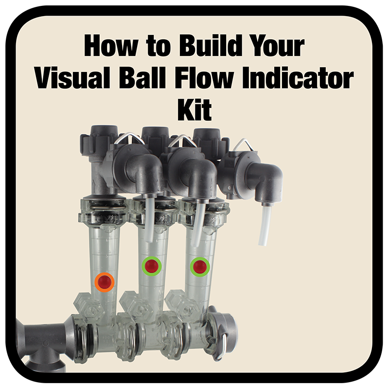
What is the best way to set up a visual ball flow indicator?
For best responsiveness and overall use, there are a few tips and tricks that will make it easier to plan and build a flow indicator kit without having to plan out too much.
That being said, there are a whole host of ways to make flow indicator manifolds up, and the below are just some guidelines and examples of what is a consistent way to build a flow indicator system.
Some Real Life Customer Examples for different configurations of Visual Flow Indicators
For a good example of how to plan out a visual flow indicator system, follow ALPINE’s Matt Mazer, as he walks through a real life example of setting a liquid manifold kit.
This can stand as a good visual walkthrough prior to getting into the guide.
Follow Matt Mazer, as he shows how to use a isolated feed flow indicator on ALPINE’s Innoculant/Chemical Injector Kit, which can be used in adding doses of additives to fertilizer while planting.
This video from the fine folks at C&R Supply show a basic assembly of a visual flow indicator manifold.
This video from the fine folks at C&R Supply shows what you can expect from your ball flow indicator in action.
STEP 1: Determing Required Flow Rate for your Columns & Which Balls to Use
The first set in building a flow indicator setup, is determining which size of column to be used.
Wilger makes 3 different ‘column sizes‘, which are used to give the best visual responsiveness to variation in flow.
Either determine your flow rate required (in US Gallons/minute) and choose the flow column that best matches your overall flow rates across all of your applications, or use the [excel-based] flow indicator column to calculate your flow rate, as well as show which columns can be used.
| Ultra Low Flow | Low Flow | Standard Flow |
|---|---|---|
| [#20475-X0 series] | [#20470-X0 series] | [#20460-X0 series] |
| Monitored Flow Range | Monitored Flow Range | Monitored Flow Range |
| 0.01 – 0.24 US gpm | 0.05 – 0.65 US gpm | 0.07 – 2.7 US gpm |
PRO TIP: If you find your travel speed or flow rate vary enough that determining flow blockages can not be achieved over the full range, try using two balls in the column at the same time to cover your variation in flow. Simply place the heavier ball (of the two) at the bottom, and the lighter ball on top.
Which Balls to Use?
Each ball is suspended at different flow rates with the different sizes of columns, so it is important to understand which ball will work best for your application.
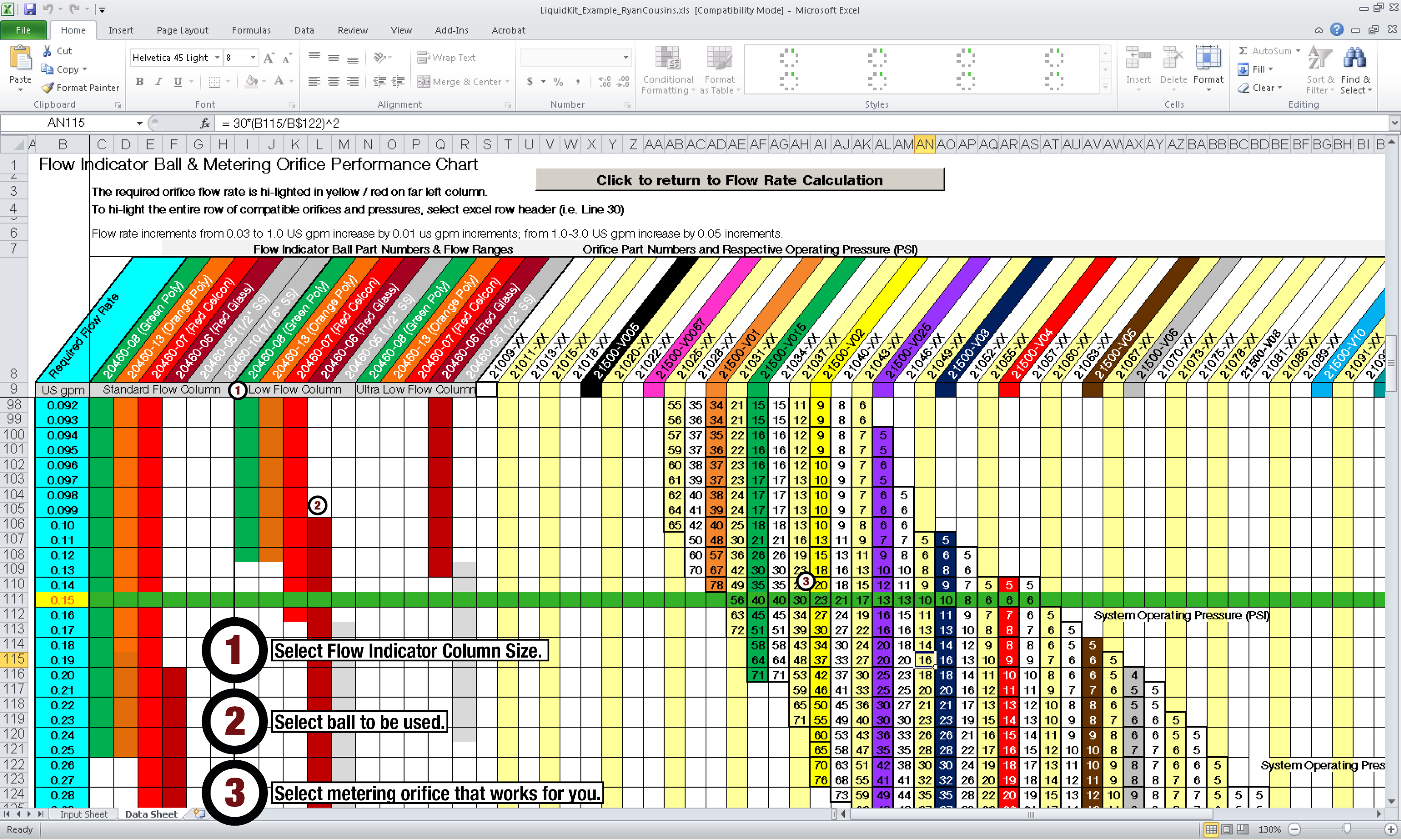
With the picture provided (shows the Wilger Flow Indicator Flow Calculator Excel Spreadsheet), it provides a line across the different flow rates, as well as the respective flow indicator column size and ball performance with those columns and flow rates. The shown information is provided based on using water at room temperature, so it can vary from field results; however, it provides a good indication of how a ball will perform with your application.
Take special attention of where the different balls enter into the ‘operating flow range’ that you are applying. If the ball’s range begins right at the same flow rate you are applying, the ball may be suspended fairly low on the flow column. If a ball is maxed out in it’s operating range at your flow rate, the ball may be suspended high on the flow column.
STEP 2: Determine How Many Flow Indicator Manifold Banks Are Needed
Depending on the layout of the application equipment, there may be existing configurations to plan around.
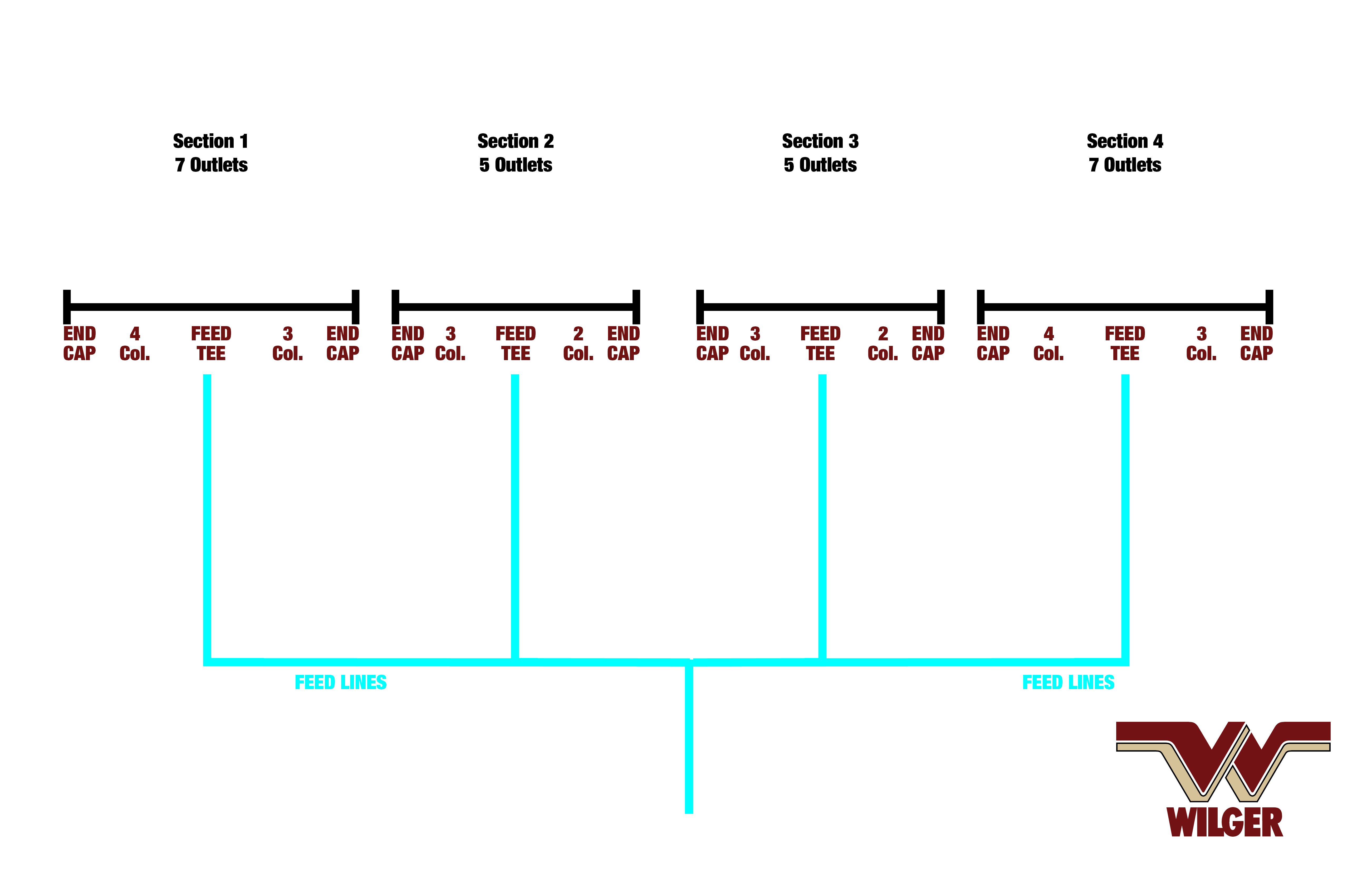
For example, if a air drill has 24 runs/openers, and it is split into four sections (7 run+ 5 run + 5 run + 7 run), you would ideally have 4 different manifold banks, with the required number of flow indicators per bank.
It makes things simpler to designate how many manifold banks are needed, as you can quickly determine how many feed lines, feed fittings and caps that you’d need to complete the setup.
For this example blueprint (showing only columns, feeds & end caps), it is clear that 24 flow columns, 4 feed tees, and 8 end caps are required to be ordered.
STEP 3: Compile list of Feed/End Cap Parts
There are a number of flow indicator inlet options available, from straight & 90° hose barbs to feed tees.
Feed Tee Parts
There are several options for inlets, but for this example, we will focus on a few commonly used FEED Tees.
For Tee Feeds, there are two styles available, 1″ NPT-F threaded inlet TEE or O-Ring seal (ORS) fitting inlet TEE
With either of the above styles, there is an option to have a blind 1/4″ NPT-F port, for the installation of a pressure gauge (if required – just drill out the 1/4″ port).
For this example, we will use the #20526-00 ORS Tee with 1/4″ NPT-F port.
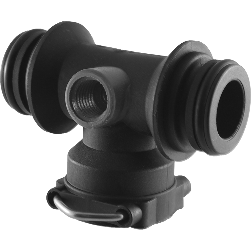
| ORS TEE w/ 1/4″ NPT Port | ORS TEE |
|---|---|
| #20526-00 | #20522-00 |
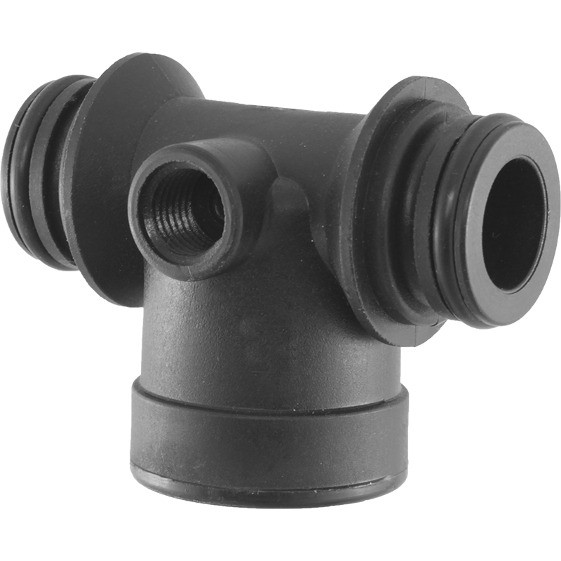
| 1″ NPT x ORS TEE w/ 1/4″ NPT Port |
|---|
| #20525-00 |
Each flow indicator has a O-Ring Seal Male end (ORS-M), which requires to be capped off. For manifolds with feed tees, two ORS-M ends will need to be capped.
End Cap Parts
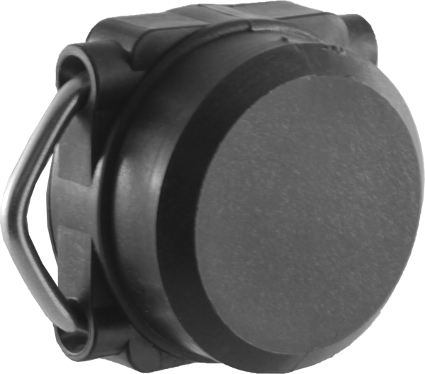
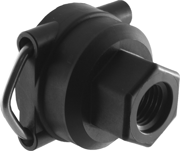
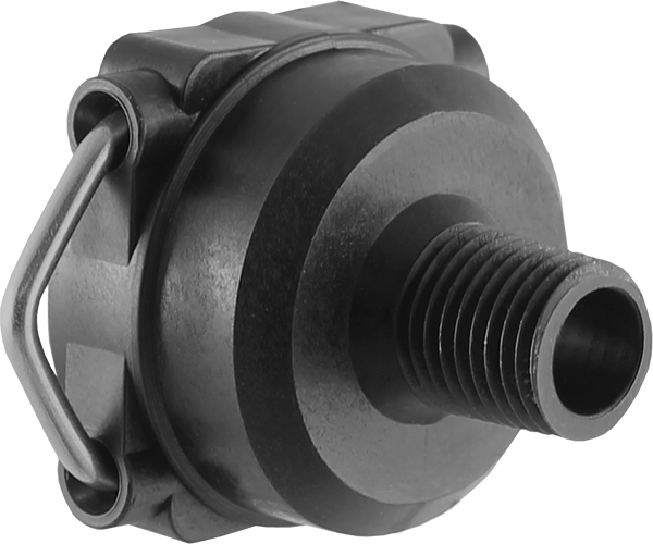
There are a few different options for end caps, from basic end caps, to ones that provide extra function, line installing pressure gauges in the side of a manifold.
| Plug Cap | Cap w/ Female Thread | Cap w/ Male Thread |
|---|---|---|
| #20521-00 | #20535-00 [1/4″ NPT] | #20530-00 [1/4″ NPT] |
| #20536-00 [3/8″ NPT] | ||
| #20537-00 [1/2″ NPT] |
STEP 4: [Optional] Choose Check Valve Style & Metering Orifice
For the best flow indicator setup, to provide the most accurate response of the balls, and being able to meter and control the flow at the manifold bank, using the ORS Check Valves are recommended.
With two outlet styles available (‘ORS to ORS‘ and ‘ORS to Combo-Jet Cap‘), we will focus only on the ORS to ORS style.
For either style of ORS check valve, there are a few different styles of control modules that can be interchanged, depending on the use of the flow indicator system.
As a recommendation, the ORS to ORS check valve with a manual on/off control module (#20551-X0 series), is the recommended option, for the best versatility for every application.
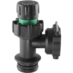
ORS to ORS Manual ON/OFF Check Valve
When the #20551-00 check valve is open, or ‘ON’, it acts as a 10 PSI check valve (other pressure versions avail.)
When it is closed, or ‘OFF’, it turns off flow to that outlet, allowing for any maintenance, such as changing out ORS metering orifices, or turning off liquid flow to certain rows on command.
Using a metering orifice directly after the flow indicator manifold provides a powerful and compact option for metering your flow to each opener from a few centralized areas. As such, Wilger manufacturs both a precision molded and drilled ORS Metering orifice that is O-ring sealed. They fit into any ORS outlet or fitting, allowing versatility with whichever flow indicator or ORS manifold setup you might use.
As there are a number of ORS metering orifice sizes, use the Wilger Flow Indicator Flow Calculator (same link as above) to make it easy to select the best orifice that with match the operating pressure and speeds you are wanting to apply at.
STEP 5: Choose Flow Indicator Outlets
Each Flow Indicator, or ORS component that has a female ORS port is compatible with ALL Flow indicator outlets. (The same is true for all ORS to ORS check valves)
As such, there is a large offering of different styles of outlet fittings, in different sizes from 1/4″ to 3/4″.
For the purpose of this example, the 1/4″ push-in tube ORS fitting would be used. For all the other ORS outlets, find them on page 15 of the Wilger Catalog.
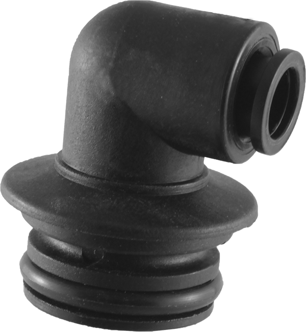
As all O-Ring Seal (ORS) fittings can be swiveled 360°, it removes any strain from hoses buckling, having to match up threads, or even unthreading anything for maintenance. They have definitely become the favorite compact manifold setup.
Now that all components are ordered, putting it together is simple. To make it even easier, apply a small amount of lubricant (e.g. liquid silicone) to the o-ring when fitting the components together to make it even easier.


